
(Information in English only - Oplysninger er kun på engelsk)
To solve a thermal problem, we need to know several parameters. Further data can then be determined.
The six most important parameters include:
If the flow rate, specific heat and temperature difference on one side are known, the heat load can be calculated.
The heat load of a heat exchanger can be derived from the following two formulas:
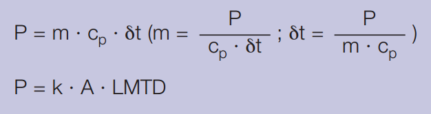
P = heat load (btu/h)
m = mass flow rate (lb/h)
cp = specific heat (btu/lb °F)
δt = temperature difference between inlet and outlet on one side (°F)
k = heat transfer coefficient (btu/ft2 h °F)
A = heat transfer area (ft2)
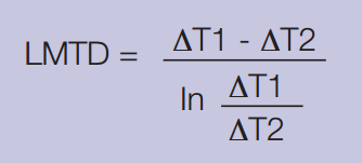
LMTD = log mean temperature difference
T1 = Inlet temperature - hot side
T2 = Outlet temperature - hot side
T3 = Inlet temperature - cold side
T4 = Outlet temperature - cold side
The total overall heat transfer coefficient k is defined as:
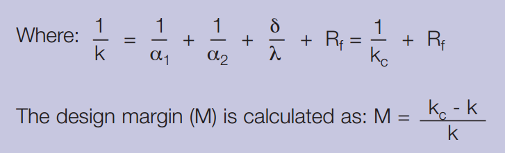
α1 = The heat transfer coefficient between the warm medium and the heat transfer surface (btu/ft2 h °F)
α2 = The heat transfer coefficient between the heat transfer surface and the cold medium (btu/ft2 h °F)
δ = The thickness of the heat transfer surface (ft)
Rf = The fouling factor (ft2 h °F/btu)
λ = The thermal conductivity of the material separating the medias (btu/ft h °F)
kc = Clean heat transfer coefficient (Rf=0) (btu/ft2 h °F)
k = Design heat transfer coefficient (btu/ft2 h °F)
M = Design Margin (%)
Combination of these two formulas gives: M = kc · Rf
i.e the higher kc value, the lower Rf-value to achieve the same design margin.
For a more complete explanation of heat transfer theory and calculations, download the following brochure:
The theory behind heat transfer
Contact us and we'll connect you with a plate heat exchanger engineer that can help you with your calculations.
![]()